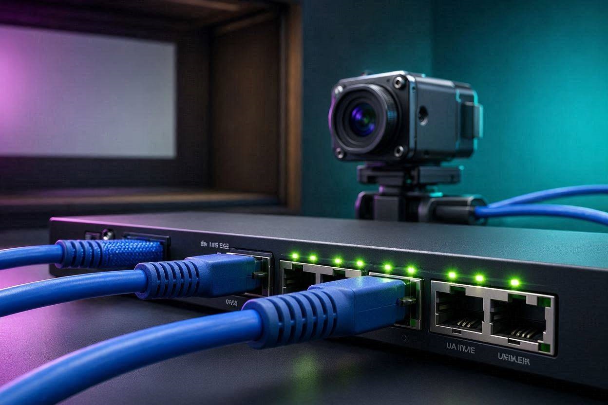
Are you struggling with stuttering video playback, dropped frames, or constant camera disconnects during your swing analysis? Setting up flawless PoE switch networking for golf simulator cameras is the most critical, yet frequently misunderstood, foundational step for any high-end indoor golf studio. Most users assume they can just plug industrial GigE Vision cameras into a standard, cheap unmanaged switch from a big-box store and expect pristine 320 FPS slow-motion footage. The reality is that high-speed, global shutter cameras transmitting uncompressed video data will instantly choke a poorly configured network, resulting in software crashes, clock drift, and missing impact frames. To capture a clubhead moving at 120 mph with absolute clarity, your digital infrastructure must be engineered with the same precision as your physical simulator build.
The “Quick Answer” / Key Takeaways Box
- Jumbo Frames are Mandatory: Your network switch and PCIe Network Interface Card (NIC) must support and be explicitly configured for 9KB (9000 MTU) Jumbo Frames to prevent catastrophic packet loss and frame dropping.
- Dedicated Bandwidth is King: High-speed cameras streaming raw, uncompressed video easily overwhelm shared network topologies; isolate camera traffic on a dedicated physical network or dedicated PCIe NIC ports.
- Power Budget Matters: Ensure your switch adheres to IEEE 802.3af (15.4W) or 802.3at (PoE+ 30W) standards with enough total wattage budget to power multiple cameras simultaneously without voltage sags.
- Interrupt Moderation: Network adapter drivers must be manually configured to handle high-frequency data interrupts, typically setting the interrupt moderation rate to “Extreme” or “High” to stabilize CPU loads.
- Link Speed Verification: A damaged cable or improper configuration can force a Gigabit (1000 Mbps) connection to automatically downgrade to Fast Ethernet (100 Mbps), immediately crashing high-framerate streams.
Why PoE Switch Networking for Golf Simulator Cameras is Fundamentally Different
When building a simulator, it is easy to underestimate the sheer volume of data generated by multi-camera setups. Unlike streaming a movie or downloading a large file, the traffic generated by industrial swing cameras operates under fundamentally different rules.
The GigE Vision Protocol vs. Standard Traffic
Standard network traffic utilizes the TCP/IP protocol, which inherently features error checking and packet retransmission. If a packet of data is lost while loading a webpage, the receiving computer simply asks the router to send it again. The user rarely notices the delay. However, PoE switch networking for golf simulator cameras relies on the GigE Vision interface standard, which transmits data via the UDP (User Datagram Protocol). UDP is designed for extreme speed and real-time streaming; it fires data packets continuously without waiting for an acknowledgment from the receiver. If a packet is lost due to a network bottleneck, it is gone forever. In the context of swing analysis, a single dropped packet corrupts an entire frame of video. When analyzing the exact moment of impact to check face angle or dynamic loft, a dropped frame renders the entire recording useless.
Bandwidth Calculations at 320 FPS
Consider the mathematical reality of a high-end setup utilizing a Sony IMX273 global shutter sensor. Running a camera at a resolution of 720 × 540 pixels at 320 frames per second generates an enormous amount of uncompressed data. A single frame consists of roughly 388,800 pixels. At 8 bits per pixel, that is over 3 Megabits per frame. Multiply that by 320 frames per second, and a single camera demands over 900 Mbps of continuous bandwidth. A standard Gigabit Ethernet port has a theoretical maximum bandwidth of 1000 Mbps. Therefore, running just two of these cameras through a single shared Gigabit uplink to your PC will result in immediate data collisions and massive frame drops.
The Core Hardware Specifications You Cannot Ignore
To build a resilient network for your tracking system, you must look past basic marketing jargon and focus on specific engineering tolerances.
IEEE Standards: 802.3af vs. 802.3at (PoE+)
Power over Ethernet (PoE) allows a single Cat6 cable to provide both data and electrical power to your cameras, eliminating the need for bulky AC adapters mounted to your simulator ceiling. However, not all PoE is created equal. Standard PoE (IEEE 802.3af) delivers up to 15.4 watts of DC power per port. For basic cameras, this is often sufficient. However, high-speed machine vision cameras with active cooling elements or integrated LED synchronization triggers require more juice. PoE+ (IEEE 802.3at) provides up to 30 watts per port. When selecting your hardware, you must calculate the total “PoE Budget.” A 4-port switch might advertise PoE capabilities, but if its total power budget is only 45W, plugging in four 12W cameras will cause random ports to shut down as the switch protects itself from overloading.
Packet Buffers and Micro-Bursts
When two or more cameras are triggered simultaneously via software or an audio microphone, they fire their data payloads at the exact same microsecond. This creates a “micro-burst” on the network. If multiple GigE streams converge on a single network switch before heading to the PC, the switch must momentarily store the overlapping data in its internal memory. This memory is called the packet buffer. Cheap switches have minuscule packet buffers (e.g., 128 KB or 256 KB). When a micro-burst hits, the small buffer overflows instantly, and the switch literally throws the excess packets in the trash. You must look for switches that explicitly feature deep packet buffers to handle heavy UDP streaming loads.
The 9KB Jumbo Frame Imperative
Perhaps the single most critical setting in PoE switch networking for golf simulator cameras is the configuration of the Maximum Transmission Unit (MTU).
Why 1500 MTU Causes Dropped Frames
By default, standard Ethernet networks are configured to use an MTU of 1500 bytes. This means that a large image file sent from the camera to the PC is chopped up into thousands of tiny 1500-byte pieces. For every piece, the computer’s processor must intercept it, process the header, and reassemble the image. At 320 frames per second, the sheer number of tiny packets overwhelms the CPU and the network interface card’s processing capabilities. The solution is Jumbo Frames. By increasing the MTU size to 9000 bytes (9KB), you allow the camera to send data in massive chunks. This dramatically reduces the overhead on the network and drastically lowers CPU utilization on your simulator PC. However, Jumbo Frames must be explicitly enabled on every device in the chain. If your PC’s network card is set to 9KB, but your unmanaged switch only supports standard 1500 MTU frames, the switch will drop the oversized packets, resulting in a completely black screen or a permanently disconnected camera.
The Premium Upgrade: Bulletproof Your Network Topology
To permanently resolve latency, dropped frames, and hardware lockups, you must abandon consumer-grade networking gear and adopt a professional topology.
Ditching Unmanaged Switches for Dedicated Hardware
The ultimate solution for high-speed camera integration is to bypass intermediate switches entirely and connect the cameras directly to dedicated hardware inside the PC. Do not plug your cameras into the same router or switch that provides internet to your house. The constant background chatter of smart TVs, phones, and IoT devices will introduce latency spikes that ruin video synchronization.
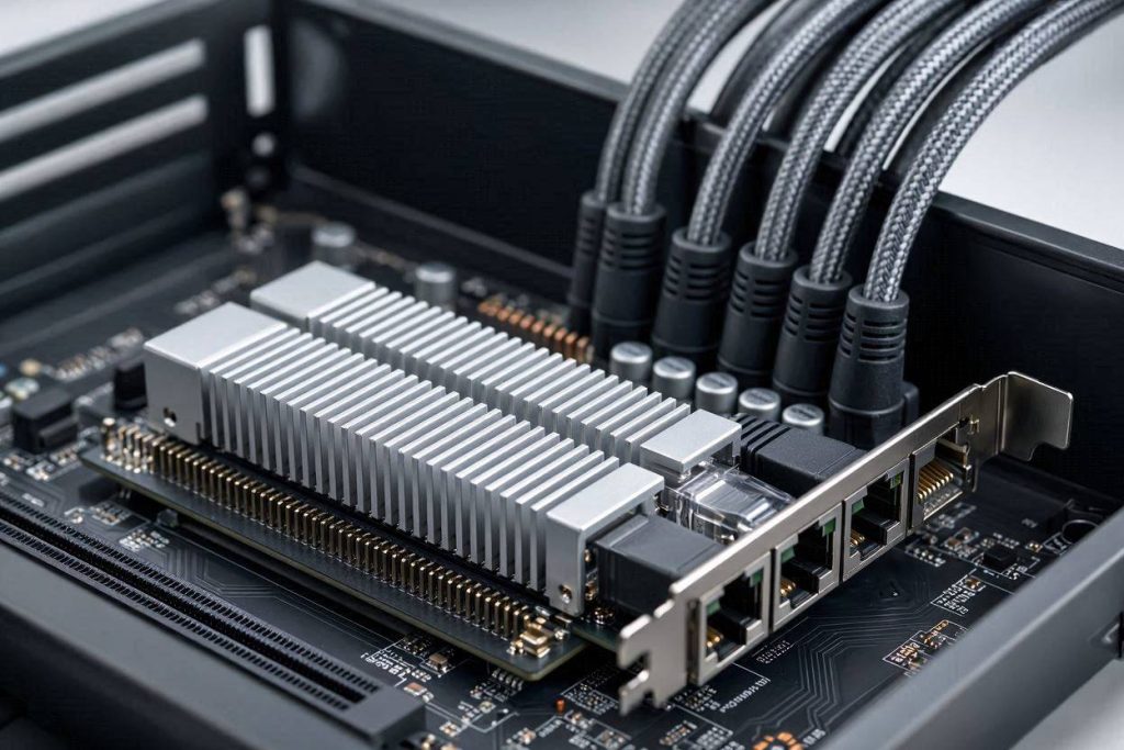
Instead, install a dedicated multi-port PCIe Network Interface Card. Hardware solutions such as the Intel Pro 1000 PT Quad Port, or industrial cards like the Adlink GIE72/74 (which feature built-in PoE power delivery directly from the PCIe slot), ensure that each camera has its own independent 1000 Mbps pipeline straight to the motherboard. By utilizing a Quad-Port PCIe card, you guarantee that a “Face On” camera and a “Down The Line” camera never have to fight for bandwidth on a shared cable.
[EXTERNAL LINK: Official IEEE 802.3 Ethernet Standards Documentation]
Interrupt Moderation and Filter Drivers
Even with the best hardware, software configuration is paramount. When installing a dedicated network card, you must dive into the Windows Device Manager to configure the adapter properties. First, ensure you install the specific “filter driver” provided by the camera manufacturer (e.g., the Spinnaker SDK for FLIR cameras, or the proprietary drivers for AVT/IDS models). This specialized software intercepts the GigE Vision traffic at the kernel level, bypassing the standard, sluggish Windows network stack. Secondly, locate the “Interrupt Moderation” setting. Set the rate to “Extreme” or “High.” This groups the hardware interrupts together, preventing the PC’s processor from being constantly overwhelmed by individual data packets, ensuring smooth playback alongside heavy 3D simulation software.
Step-by-Step Troubleshooting Guide for Frame Drops
If you are experiencing intermittent issues, follow this strict diagnostic protocol to isolate the point of failure in your PoE switch networking for golf simulator cameras.
Checking Link Speeds (1000 Mbps vs 100 Mbps)
The most common cause of sudden frame drops is a degraded physical connection. If a cable is crimped, bent too sharply, or suffering from electromagnetic interference, the network cards will automatically negotiate the link speed down from 1000 Mbps to 100 Mbps to maintain stability. Check the camera settings in your analysis software. If the “Device Link Speed” shows 100 Mbps, your bandwidth has just been slashed by 90%. To fix this, inspect the physical RJ45 connectors, ensure the cable is fully seated, or replace the ethernet run entirely. You can also verify the link speed by checking the status of the network adapter via the Windows Control Panel.
Adjusting GEV SCPD Settings
If your cameras share a network path (which is highly discouraged, but sometimes physically necessary), you must manage packet collisions manually. Within the advanced camera settings under the Device/Link section, look for the Stream Channel Packet Delay (GEV SCPD) or Inter-Packet Delay parameter. This setting forces the camera to wait a specified number of microseconds between sending packets. By increasing the SCPD value (e.g., setting it to 150 or higher), you slow down the data transmission rate slightly, allowing the switch’s packet buffer time to clear. While this may slightly reduce your maximum achievable frame rate, it creates a perfectly stable, error-free video stream.
[INTERNAL LINK: The Ultimate Guide to Launch Monitor Data Synchronization]
Cabling: The Silent Killer of Camera Networks
The physical cables transmitting the data are just as critical as the silicon processing it. Golf simulator environments are incredibly hostile to networking equipment.
Cat6 vs Cat6a Shielding (FTP vs STP)
Between massive projector power supplies, high-intensity LED lighting arrays, and radar-based launch monitors emitting continuous radio frequencies, the amount of Electromagnetic Interference (EMI) in a simulator bay is staggering. Running standard, unshielded Cat5e cables alongside power conduits is a recipe for disaster. The EMI will induce cross-talk and data corruption within the ethernet cable.
You must utilize Cat6a Shielded Twisted Pair (STP) or Foiled Twisted Pair (FTP) cabling. Shielded cables feature a metallic foil wrapping around the internal copper wires that deflects external interference. Furthermore, the shielding must be properly grounded using specialized metal-shielded RJ45 connectors. If the cable is shielded but the connector is plastic, the EMI has nowhere to vent, and the shielding acts as an antenna, actually making the interference worse.
Preventative Maintenance & The Simulator Network Checklist
To ensure your system remains highly operational, treat your network infrastructure with the same care as your launch monitor.
- Thermal Management: PoE switches generate significant heat. Do not bury your hardware inside an unventilated wooden cabinet behind your hitting screen. Ensure active airflow over the switch chassis.
- Driver Hygiene: Disable automatic Windows updates for your dedicated PCIe network cards. A generic Windows driver update can silently overwrite your specialized GigE filter drivers, instantly breaking your camera setup.
- Cable Strain Relief: Ensure that the ethernet cables plugging into your cameras have proper strain relief. The repeated vibrations from hitting golf balls into the screen can slowly rattle connectors loose over time.
- IP Address Isolation: Always assign static IP addresses to your cameras (e.g., 10.0.1.10 for Camera 1, 10.0.2.10 for Camera 2) on an entirely different subnet than your home’s Wi-Fi router. This guarantees zero IP conflicts and instantaneous camera discovery upon software boot.