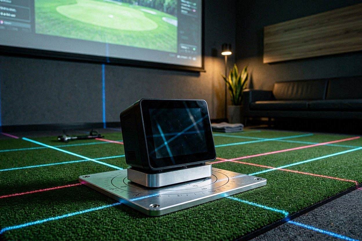
Photometric launch monitors are beautifully precise instruments, but their data is only as good as their spatial orientation. If your unit is resting even a fraction of an inch lower than your actual hitting turf, or if its tilt axis is slightly off, the unit’s dimple-tracking cameras will output warped launch angles, inflated spin metrics, or highly frustrating “no-reads.”
Achieving exact, true-to-life numbers inside a hitting cage or a full golf simulator bay requires systematic optimization. This comprehensive operational guide breaks down the exact physical leveling procedures, software matrix updates, and structural math variables needed for calibrating the Uneekor Eye Mini for indoor mat accuracy.
1. Eliminate the Structural Height Disparity (The Base Layer Offset)
The absolute foundation of calibrating the Uneekor Eye Mini for indoor mat accuracy is balancing the physical plane between the machine’s base and the golf ball. Photometric monitors calculate the initial vertical launch angle based on the assumption that the ball is resting on a perfectly flat horizon line relative to its optical lenses.
If you place the launch monitor directly on a concrete garage floor while hitting off a premium, thick mat like a Real Feel Country Club Elite or a TrueStrike section, the ball is elevated between 1.75 to 2.0 inches above the camera’s baseline. This height delta severely distorts the internal vertical tracking matrix. The camera captures the ball exiting the frame higher than expected, causing the internal algorithms to read an artificially high launch angle and erratic spin values.
To isolate this hardware problem, you must construct or purchase a rigid spacer platform for the device. The base of the unit must sit perfectly flush with the top layer of the synthetic turf fibers where the ball rests. Do not use soft foam blocks or layers of uneven cardboard; under the heavy vibrations of repeated iron strikes, non-rigid surfaces will shift, causing the monitor to subtly tilt forward or backward mid-session. Use a solid wood block, a dedicated polymer spacer plate, or a modular frame to build a structural platform that secures the device at the identical vertical height as your hitting strip.
2. Execute Leveling Board Calibration
Once the hardware platform matches the vertical height of your hitting mat, you must address pitch, roll, and yaw. Even if your spacer plate looks visually straight, concrete subfloors are notoriously sloped for water drainage, particularly in home garages. A slope of just 1° translates to significant errors downrange in your simulator software.
The device features an internal tilt sensor, but manual physical calibration is required to lock in flawless data.
- The Leveling Target Board: Retrieve the official checkered calibration board provided by the manufacturer. Place this board completely flat across your hitting zone, directly over the exact spot where you intend to place the golf ball.
- Chassis Adjustments: Turn on the monitor and look at the physical leveling bubble or the digital alignment wizard on the built-in screen. Adjust the heavy-duty threaded feet at the bottom of the device until the internal sensors register a perfect 0.0° pitch (forward/backward tilt) and 0.0° roll (side-to-side tilt).
- Verification: A completely level chassis ensures that when the dual global-shutter cameras capture the dimple rotation vectors, the horizontal tracking vector aligns perfectly with the absolute geometric horizon of the room.
3. Map the Hitting Zone Coordinates in VIEW Software
With the hardware physically stabilized, boot up your dedicated PC and launch the official VIEW software suite. Navigate immediately to the settings panel to verify the camera’s optical region of interest (ROI).
The unit features a defined tracking zone measuring roughly 12 inches wide by 8 inches long. Inside the software’s calibration screen, you will be presented with a live visual feed from the internal tracking cameras. Place a ball in the center of your hitting mat and look at the overlay grid on your PC monitor.
The ball must be located squarely within the highlighted green tracking box. If the ball rests too close to the edge of the optical frame, the cameras will fail to capture the critical first 12 inches of ball travel before it exits the tracking volume. Adjust the physical position of the unit closer to or further from the mat until the ball sits squarely dead-center in the digital viewport. Secure the position by marking the floor or setting up a structural guide block so the device can be placed back in this exact location every session.
[IMAGE PLACEHOLDER: Screenshot of the digital camera alignment window showing a golf ball perfectly centered within the tracking coordinates + Alt Text: Calibrating the Uneekor Eye Mini for indoor mat accuracy using the digital grid configuration screen]
4. Account for Turf Compression Vectors
One of the most overlooked variables when calibrating the Uneekor Eye Mini for indoor mat accuracy is dynamic turf compression under load. When a golf ball sits passively on a dense nylon mat, it rests at a specific altitude. However, when a player steps onto the mat and delivers a heavy downward iron blow, the dense foam backing or gel subsurface undergoes momentary mechanical compression.
If your mat is highly compliant (like a gel-based or deep-pile fiber system), the clubhead will depress the hitting strip downwards by several millimeters at the microsecond of impact. A standard calibration routine does not account for this dynamic movement.
To calibrate for this variable, perform a sequence of test shots using a high-lofted wedge. Review the raw launch parameters in the software. If you notice that your high-lofted wedges are consistently generating launch angles that are 2 to 3 degrees lower than your real-world ball flight numbers, it indicates that the ball is compressing deep into the turf before the camera locks its primary vector tracking points. To fix this in the software, you can apply a subtle software offset or micro-adjust the physical height of the monitor’s spacer platform down by 2mm to perfectly compensate for the dynamic compression vector of your specific brand of turf.
5. Clean Light Pollution from the Optical Window
Because the unit relies on high-speed infrared cameras to run its Dimple Optix processing algorithms, visual noise within the tracking zone will completely ruin your calibration settings. Before running a final accuracy check, you must perform ambient light checking.
Scan your hitting bay for any reflective surfaces that fall within the camera’s immediate field of view. Reflective chrome details on your golf shoes, white clubhead finishes that pick up ambient glare, or direct sunlight leaking through garage door seals can cast stray IR wavelengths into the global-shutter sensors.
Clean the physical camera glass thoroughly using a dedicated lens care checklist. Dust, loose nylon fibers from synthetic mats, and ball cover residue will cloud the optical window, reducing image contrast and causing structural calculation errors or sudden no-reads.
[EXTERNAL LINK: Detailed technical analysis of how ambient infrared interference creates artifacts in global shutter image sensors]
6. Run the Final Verification Matrix
To guarantee your calibration protocol has successfully locked in absolute indoor accuracy, you must run a structured benchmark testing matrix. Do not rely on subjective feel; look purely at the physical data outputs.
Grab three distinct clubs from your bag: a standard pitching wedge, a 7-iron, and your driver. Hit five shots with each club using high-quality, clean golf balls that feature prominent logos or clear alignment markings to give the Dimple Optix software maximum tracking contrast.
| Target Club | Ball Metric Focus | Target Indoor Calibration Benchmark |
| Pitching Wedge | Vertical Launch Angle & Backspin | Launch angle should perfectly match the structural dynamic loft of the club with zero mat-skipping anomalies. |
| 7-Iron | Spin Axis & Smash Factor | Spin axis should hover near 0.0° on clean center strikes. Consistent positive or negative tilt indicates a yaw misalignment of the chassis housing. |
| Driver | Launch Angle & Total RPM | Low backspin (~2000-2500 RPM) with high ball speed. Artificial spikes in spin indicate height calculation mismatches over the mat canopy. |
If your data falls precisely within these logical standard ball flight parameters, your spatial calibration is fully dialed in. If you observe systematic anomalies—such as every single club showing a slight rightward push despite clean center strikes—loosen the alignment housing and subtly adjust the yaw angle of the monitor until the target line matches your physical impact screen perfectly.
7. Lock Down Your Connection and Finalize Software Bridging
The final stage of securing accuracy across your entire simulator environment involves the data connection pipeline. Once the machine is tracking accurately inside the native VIEW software, you must ensure this clean data transfers to third-party simulation programs without latency or data corruption.
Always run a dedicated, high-quality CAT6 Ethernet cable directly from the device to your simulator PC. While Wi-Fi connections are convenient, wireless networks in homes and garages are highly susceptible to packet drops and localized interference. A hardwired connection guarantees that the massive data arrays generated by the dual cameras are instantly pushed to your graphics card, rendering a smooth ball flight path on the screen the exact millisecond your club breaks the infrared tracking zone.
[INTERNAL LINK: 7 Technical Specs for the Best Golf Simulator Hitting Mats in 2026: Injury Prevention Guide]
The Simulator Upgrade
Perfect calibration means nothing if your support hardware cannot keep pace with the real-time processing requirements of modern golf tracking software. When running data-heavy simulator applications alongside high-speed camera software, standard desktop computers will stutter, causing massive visual lag on your impact screen.
To guarantee your system renders every calculation with zero frames of latency, you must upgrade your computer core to an elite gaming rig. We highly recommend configuring a custom PC built around an Intel Core i9 processor paired with an Nvidia RTX 4080 Super graphics card. This hardware profile provides the raw graphic processing power needed to compute complex ball-flight vector mathematics instantly while pushing smooth, lifelike graphics to your projector in native 4K resolution.
Furthermore, if you want to turn this highly optimized hardware bay into a seamless, elegant installation, consider mounting your technology inside a premium enclosure kit. Retailers like Carl’s Place and The Indoor Golf Shop (both accessible via premier consumer networks like ShareASale and Impact) offer customized technology stands, protective launch monitor shields, and specialized floor panels built to accommodate the exact footprint of high-end optical tracking units. Sourcing your components through these authorized technical channels ensures that your home studio functions flawlessly as a cohesive unit.
Preventative Mat Calibration Check
To maintain absolute data integrity over long-term use, perform this quick physical audit at the start of every month:
- Mat Rotation Check: High-volume iron play will naturally cause the center hitting strip of your golf mat to wear down, creating a micro-depression in the turf fibers. Rotate your hitting panel 180 degrees every 30 days to distribute the wear evenly.
- Chassis Height Re-Verification: Check that your spacer platform hasn’t settled or warped due to ambient humidity changes. Run a straight-edge level across the hitting turf directly to the launch monitor lens plate to confirm the physical plane remains perfectly flush. A 2-minute check ensures your spin axis metrics remain flawlessly accurate year-round.
1 thought on “7 Steps to Calibrating the Uneekor Eye Mini for Indoor Mat Accuracy”