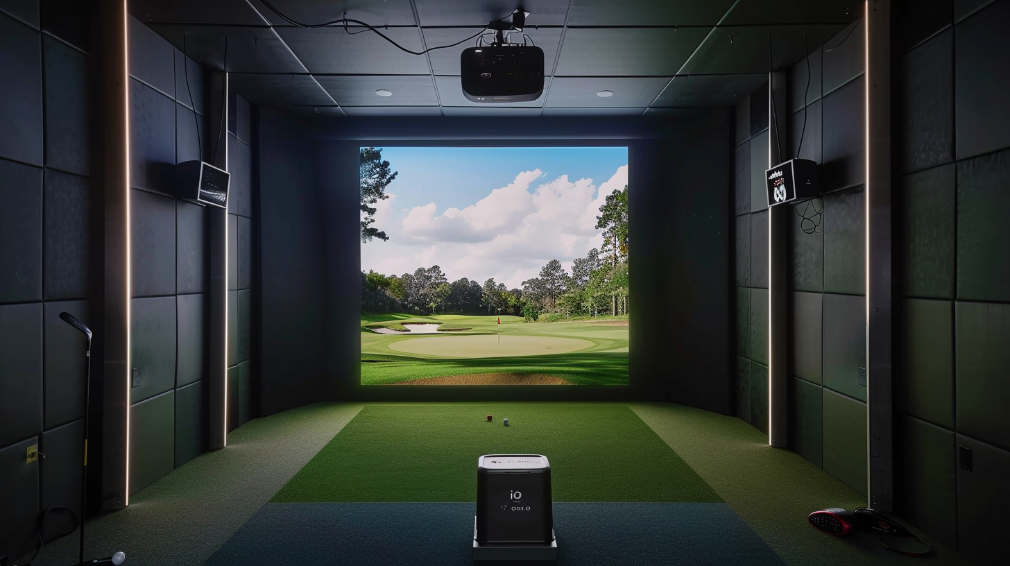
Architecting a luxury residential golf studio or launching a high-capacity commercial indoor golf center requires choosing the correct data tracking infrastructure. Overhead launch monitors have fundamentally shifted the engineering landscape of indoor golf by moving sensitive, high-ticket tracking hardware completely off the floor. This eliminates the persistent risk of physical object strikes and provides a completely open hitting environment. However, moving from traditional floor-standing units to fixed ceiling structures introduces strict parameters regarding room geometry, power delivery, and computer processing capabilities.
The entry of the Trackman iO into the overhead simulator space marks a major technical evolution for a brand built on outdoor Doppler radar. By engineering a hybrid sensor package optimized specifically for enclosed rooms, the system addresses the common tracking issues that can impact short-flight indoor setups. This detailed Trackman iO indoor review will evaluate the core sensor technology, physical installation metrics, compute specifications, and multi-user workflows to determine how this system handles premium simulation.
The Quick Answer / Key Takeaways
- Hybrid Engine Design: The hardware leverages Optically Enhanced Radar Tracking (OERT), a synchronous configuration blending a 4,600 FPS camera with low-range dual Doppler radar tracking antennas.
- Symmetrical Multi-User Playback: The overhead mounting architecture creates a broad, open hitting envelope that supports both left-handed and right-handed golfers without physical device shifting.
- Strict Computing Restrictions: The platform requires an Intel Core i7 or i9 processing core; AMD processing platforms are fundamentally unsupported by the driver architecture.
- Stickerless Ball Flight Verification: The internal tracking software processes ball flight vectors natively using dimple recognition, removing the requirement for specialty marked balls or stickers during practice.
- Rigid Spatial Constraints: The enclosure must provide an absolute minimum ceiling height of 9 feet 4 inches, with an exact 3.5-foot forward mounting offset measured directly from the tee position.
Technical Sensor Architecture: Deconstructing OERT
To evaluate this hardware, you must analyze the underlying physics that occur during the sub-millisecond event of a golf swing inside an enclosed room. Traditional tracking radar requires a massive longitudinal path to watch a ball displace through space to calculate true spin decay and aerodynamic axis tilt. When ball flight is cut short by an impact screen, radar hardware needs secondary sensor support to prevent estimated or calculated data profiles.
The architecture resolves this short-flight constraint by deploying a specialized technology layout known as Optically Enhanced Radar Tracking (OERT). This approach integrates dual Doppler radar antennas with a high-speed camera engine into a single ceiling-mounted housing. One radar antenna array is tuned specifically to track the club head path as it enters the lower hitting zone, capturing initial delivery angles and velocity vectors. The secondary antenna array measures initial ball launch parameters, focusing on initial ball speed and horizontal launch directions.
[IMAGE PLACEHOLDER: Technical schematic outlining the synchronized radar wave and camera tracking paths pointing down at a hitting surface + Alt Text: Technical sensor layout diagram inside a Trackman iO indoor review configuration]
Working in perfect harmony with the radar array is a high-speed camera processing engine operating at 4,600 frames per second. Backed by an integrated array of high-intensity infrared LEDs, the camera takes multiple high-contrast images of the ball’s surface within the first few inches of movement. The system uses these images to track the physical movement of the ball’s dimples or graphic logos, calculating exact total spin and true spin axis tilt instantly. By merging radar speed tracking with high-speed camera image analysis, the processing engine delivers real-time data verification without relying on downstream flight approximations.
Because the system relies on high-speed photography to calculate spin vectors, controlling ambient lighting inside your simulator bay is crucial. Excessive near-infrared light from consumer spotlights, unshielded halogen track bulbs, or light leak from high-lumens projection systems can overexpose the camera lens aperture. This overexposure can result in dropped data packets or delayed shot processing. Maintaining a clean, controlled light footprint directly over the hitting surface is essential for consistent data capture.
Physical Footprint, Weight Loads, and Mounting Protocols
Overhead tracking units require structural planning before you secure mounting hardware into ceiling joists. Disregarding the physical weight specifications or vertical dimensions of the chassis can cause performance issues from structural vibration or improper focal paths.
Enclosure Dimensions and Thermal Design
The hardware features a compact, minimalist square design engineered to install flush into modern acoustic tiles or dark multi-layer ceiling enclosures. The external chassis measures exactly 13.1 inches wide by 13.1 inches deep, with a remarkably low vertical profile of just 4.2 inches. This shallow depth helps protect the lenses from high-lofted wedges or deflecting shafts during aggressive swings.
The complete tracking assembly weighs 8.6 lbs (3.9 kg). The main structural enclosure is constructed from high-impact polymer materials integrated with an internal structural aluminum frame. This aluminum plate acts as a passive cooling heat sink for the internal motherboard layers. Because processing dual radar frequencies and 4,600 FPS images creates substantial heat, keeping the area around the casing clear of thick insulation or unventilated ceiling enclosures is vital to maintain stable processing temperatures.
Vertical and Longitudinal Installation Tolerances
Securing the mount requires strict adherence to vertical and horizontal placement guidelines. The bottom face of the optical glass lens must hang at a height between 9 feet 4 inches and 10 feet directly above your hitting turf surface. The absolute sweet spot for perfect lens focus is 9 feet 8 inches. If your ceiling height exceeds 10 feet, you must lower the mounting assembly using a rigid structural pipe drop or a heavy-duty adjustable ceiling bracket.
+--------------------------+----------------------------+----------------------------+
| Spatial Dimension        | Minimum Threshold Parameter| Maximum Allowable Limit    |
+--------------------------+----------------------------+----------------------------+
| Structural Ceiling Height| 9 Feet 4 Inches            | 10 Feet 0 Inches           |
| Forward Tee Offset       | 3 Feet 3 Inches            | 3 Feet 5 Inches            |
| Hitting Corridor Width   | 10 Feet 0 Inches           | 14 Feet+ (Optimal Multi)   |
| Hitting Screen Distance  | 10 Feet 0 Inches           | 14 Feet 0 Inches           |
+--------------------------+----------------------------+----------------------------+
Horizontally, you must place the unit centered over your primary target plane, positioned 3 feet 3 inches to 3 feet 5 inches in front of your tee position (measured closer to the screen). This specific forward offset gives the high-speed camera an un-obstructed view of the ball and the club face at impact, without the player’s head, hands, or shoulders blocking the path of the internal infrared flash array.
Symmetrical Multi-User Usability: Eliminating the Handedness Bottleneck
The primary operational advantage of implementing an overhead system like the one tested in this Trackman iO indoor review is the instant improvement in game pacing when hosting multi-player groups with mixed playing styles.
Traditional floor-standing launch monitors map data from a fixed side position relative to the golf ball. If a right-handed player finishes their turn and a left-handed player steps up into the bay, the entire tracking unit must be picked up, carried to the opposite side of the mat, re-aligned to the target screen, and re-calibrated inside the tracking software. This manual intervention slows down gameplay, interrupts match flow, and can introduce measurement variations if the hardware is not replaced on the exact same coordinate lines.
[IMAGE PLACEHOLDER: Overhead illustration of a dual-sided symmetrical hitting mat with central tracking footprint + Alt Text: Multi-user left and right-handed layout configuration using a Trackman iO indoor review system]
The overhead camera system completely removes this obstacle by shifting the optical focus directly down from above. This vantage point creates a spacious, centralized hitting zone across your premium turf mat. Left-handed and right-handed players approach the same physical tee position and swing naturally.
The software automatically tracks the direction the club enters the hitting zone, processes the ball flight data, and updates the software display instantly. This makes it an ideal configuration for commercial entertainment facilities or home simulator bays where family and friends play together.
Data Set Rigor: Captured Parameters vs Software Omissions
For high-performance training, technical club fitting, or deep instruction, you must analyze exactly what metrics the tracking hardware reads directly versus what data points are calculated using software assumptions.
Ball Launch Performance Validation
The system delivers a comprehensive collection of ball flight data points. It directly reads ball velocity, horizontal launch direction, vertical launch angle, total spin rate, spin axis tilt, and computed carry distances. Because the system’s camera engine tracks the ball cover dimples under intense infrared light, your real-world ball launch parameters are processed with absolute mathematical precision within the first few inches of flight.
While the unit can track any standard golf ball under ideal lighting conditions, utilizing Titleist Pro V1x RCT (Radar Capture Technology) golf balls provides an extra layer of data security for indoor bays. The specialized metallic print patterns embedded beneath the cover of the RCT ball act as high-visibility mirrors for the dual Doppler radar antennas, guaranteeing flawless spin validation on high-speed driver strikes or low-velocity putts.
Club Delivery Metrics and the Vertical Axis Omission
For club analysis, the hardware provides an elegant, stickerless data pipeline. Without requiring you to apply reflective markers or stickers to your club face, the dual radar sensors calculate club head speed, smash factor efficiency, club path, face angle, and face-to-path delivery profiles. This frictionless process allows players to pull any club from their bag and swing immediately without pausing to apply manual stickers.
However, you must account for a significant architectural omission regarding vertical swing tracking: the system does not measure vertical Angle of Attack (AoA). On a traditional floor-based radar unit, a secondary radar sensor sweeps the low horizontal plane behind the ball, tracking the club’s descending or ascending arc through space over several feet. Because this overhead unit is mounted high and in front of the tee, its optical and radar arrays cannot see the longitudinal entry plane required to calculate direct vertical attack angles.
If monitoring precise fractional adjustments to your vertical driver attack angle is a core focus of your coaching or personal game development, you will need to rely on the software’s derived spin loft equations to approximate your vertical path, or integrate a floor-standing quadrascopic camera array designed to capture face delivery angles directly from the side.
Computing Workstation Demands and Local IT Infrastructure
Overhead tracking units offload their high-volume image processing and radar triangulation directly to an external computer terminal. Budgeting for an underpowered workstation will result in noticeable display delays, choppy frame rates, or system instability during gameplay.
The Strict Intel Processor Requirement
The software application powering the system is built with processing code optimized exclusively for Intel hardware layouts. AMD Ryzen processors are fundamentally unsupported by the system drivers. If you attempt to connect the launch monitor to a custom gaming computer utilizing an AMD CPU, your setup will experience constant connection drops, software crashes, or a total failure to initialize the tracking cameras.
Your simulator computer must feature at least an Intel Core i7 or i9 processor from the 12th generation or higher, running a base clock frequency of 3.4 GHz. The system also requires a minimum of 32GB of system RAM and a high-speed NVMe M.2 Solid State Drive to ensure seamless texture streaming when loading detailed virtual courses.
Graphics Card Performance Thresholds
Rendering advanced virtual courses in native 4K resolution across a premium projection screen demands massive graphics processing power. To maintain a smooth, lag-free 60 frames per second at impact, your computer must meet these exact hardware standards:
* Standard 1080p Resolution: NVIDIA GeForce RTX 4070 Baseline (12GB VRAM)
* Immersive 2K Resolution: NVIDIA GeForce RTX 4070 Ti Super (16GB VRAM)
* Ultra-HD 4K Resolution: NVIDIA GeForce RTX 4080 or RTX 4090 (16GB+ VRAM)
Additionally, your computer’s motherboard must feature a dedicated, secondary Gigabit Ethernet (LAN) network interface card. The launch monitor requires an independent, un-shared hardwired network cable connection to transmit its massive optical data packets to the computer without interruption. Running the unit through an unpowered USB-to-LAN adapter or attempting to connect over standard residential Wi-Fi will introduce data bottlenecks, resulting in missed shots and processing lag.
Premium System Upgrades: Optimizing Your Hitting Space
Deploying top-tier tracking hardware inside a cheap or poorly configured hitting enclosure will significantly degrade your tracking data and risk expensive property damage. To maximize the performance of your system, your surrounding environment must be built to matching commercial standards.
Premium Strike-Forgiving Stance Mats
Overhead high-speed cameras monitor your club head as it enters the lowest point of the swing arc. Cheap, standard driving range mats feature thin nylon fibers glued directly over a hard foam backing resting on a concrete floor. When a golf club strikes this unyielding surface, the head bounces artificially off the ground.
This unnatural vertical deflection distorts your club path and face angle metrics, producing inaccurate data that does not match real grass turf interaction. To protect your data integrity, install a premium, multi-layer stance mat featuring an independent, strike-forgiving hitting strip insert. Premium inserts use deep-pile synthetic fibers designed to let the iron head move down and through the ball naturally. This ensures your indoor club metrics perfectly match your outdoor performance while protecting your wrists and joints from repetitive impact shock.
High-Density Acoustic Impact Screens
A golf ball launched at high velocity carries immense kinetic energy. To stop these balls safely and quietly, your enclosure must use an impact screen woven from premium, multi-layer polyester fibers designed for heavy impact and minimal image bleed.
The screen frame should be constructed from thick steel piping wrapped in high-density acoustic foam safety padding. The tensioning must be dialed in carefully using heavy-duty bungees or adjustable side-straps. If tensioned too tightly, the screen will act like a trampoline, rebounding golf balls back at the golfer or straight into your delicate ceiling-mounted electronics. Ensure you maintain a clean, 12-inch air gap between the back of your impact screen and any solid rear walls to allow the fabric to flex and drop the ball safely to the floor.
Pro-Level Maintenance and Calibration Protocols
Overhead tracking units are relatively low-maintenance compared to floor boxes, but they operate in harsh indoor environments filled with synthetic turf dust, floating carpet fibers, and high-impact vibrations. Implement this preventative maintenance routine to keep your tracking data perfectly calibrated.
The Cross-Line Laser Grid Realignment Hack
Even when using industrial ceiling anchors, your building’s ceiling frame will subtly expand, contract, and vibrate over the course of a year due to seasonal temperature shifts or heavy foot traffic on floors above. This micro-movement will slowly push your overhead camera sensor out of alignment with your floor mat.
To correct this mechanical drift without hiring a professional installer, implement this simple laser grid hack:
- Mount a self-leveling cross-line laser tool flat onto your center hitting turf.
- Align the forward beam to trace a line perfectly parallel to your impact screen.
- Drop a heavy-duty plumb line directly down from the physical center casing of your overhead unit.
- Check that the plumb bob touches the ground exactly at the intersection point of your laser lines.
- If the chassis has drifted off-axis by even a quarter of an inch, manually adjust the ceiling mount bracket set screws until the hardware target line aligns perfectly with your physical laser line. Performing this manual check every three months will permanently prevent tracking drift in your horizontal launch data.
Anti-Static Lens Preservation Pass
Indoor simulator bays generate immense amounts of static electricity as synthetic golf balls repeatedly strike polyester screen fibers at high speeds. This static buildup acts as a powerful invisible magnet, pulling fine nylon turf dust, carpet lint, and screen debris straight up into the air where it clings to your launch monitor’s optical glass lenses.
Never clean the delicate optical lenses of an overhead tracking unit with a basic cotton shirt, paper towel, or standard industrial microfiber rag. These materials trap tiny pieces of grit that will micro-scratch your lens’s specialized anti-reflective and anti-static coatings, permanently blurring the camera’s vision over time. Instead, use a manual DSLR rubber camera blower to dislodge loose dust under pressure, then gently clear the glass using a specialized camera-grade optical wet wipe. Keeping your lenses immaculate guarantees that your high-speed cameras never drop a tracking frame during an elite simulator session.
Pre-Flight Installation Checklist
Before launching your simulator room design or locking down your structural framework, verify that your bay complies with these essential technical parameters:
- [ ] Intel Architecture Confirmed: The computer system features an elite Intel Core i7 or i9 processing chip.
- [ ] Ceiling Height Compliant: The physical distance from the turf plane to the ceiling bracket measures between 9’4″ and 10’0″.
- [ ] Forward Offset Established: The forward tracking mount center sits exactly 3.5 feet in front of your intended tee coordinate.
- [ ] Network Infrastructure Isolated: The computer workstation has two dedicated Gigabit LAN ports to isolate the radar data stream.
- [ ] Static Mitigation Prepared: A camera lens blower and specialized anti-static wipes are stored in the bay for monthly cleaning cycles.
Custom Setup Reference Guides
- [INTERNAL LINK: How to Calibrate Your Launch Monitor for Flawless Indoor Putting Setup Profiles]
- [EXTERNAL LINK: Official STG Hardware Alignment and Enclosure Clearance Structural Specifications]”