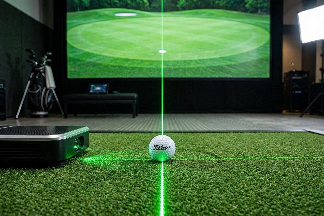
Dialing in your indoor golf simulator for high-velocity driver strikes and high-spin wedge plays is relatively straightforward. However, configuring your tracking systems to accurately read a low-velocity, micro-spin four-foot putt remains one of the greatest engineering hurdles for custom simulator builders. If your system frequently drops putts, experiences frustrating data lag, or consistently pushes your short putts offline, your environmental tracking boundaries are out of alignment.
Achieving tour-grade short game accuracy indoors requires shifting your focus from overall swing mechanics to micro-telemetry calibration. Whether your bay relies on a dual-radar array, a floor photometric chassis, or an overhead infrared system, the digital parameters must be perfectly tuned to capture low-speed rolling physics. This highly technical guide will walk you through the precise physical alignments, lighting adjustments, and software configurations required to eliminate missed reads permanently.
The Quick Answer / Key Takeaways
- The Core Issue: Missed or inaccurate putts are almost always caused by poor physical alignment, incorrect camera tilt angles, or ambient infrared light interference rather than broken hardware.
- Horizontal Launch Precision: A hardware misalignment of just 0.5 degrees will translate into a completely missed cup on a standard eight-foot virtual putt.
- Lighting Optimization thresholds: High-speed photometric lenses require controlled ambient lighting, typically under 300 lux, to prevent the sensor from losing track of ball dimples at slow speeds.
- Substrate Resistance Mapping: Your software profile must be adjusted to match the physical rolling resistance of your turf mat, using accurate rolling coefficient multipliers.
- Firmware Updates: Ensure your launch monitor’s internal processing units are updated to support low-velocity threshold tracking data streams.
The Physics of Low-Velocity Ball Tracking Indoors
To resolve tracking errors on short putts, you must understand how launch monitors shift their algorithmic tracking profiles when you switch from a full swing to a putter. High-speed full swings create massive structural changes and visible high-contrast movement frames. A soft putt, by contrast, creates minimal initial velocity and subtle face-compression characteristics.
Photometric ground systems and overhead camera arrays calculate launch angles by looking at the high-contrast displacement of the ball cover over a sequence of microseconds. When a ball rolls slowly, the frame-to-frame change is incredibly small. If your physical alignment is slightly off-axis, or if the camera’s lens configuration cannot distinguish the ball cover from your putting turf, the software processing engine drops the shot cycle completely.
Radar-based tracking systems face an entirely different set of physical hurdles indoors. Radar tracks objects by analyzing the Doppler frequency shift of radio waves bouncing off a moving target. Because a putted ball moves slowly and stays close to the floor, the radar reflections can easily become mixed with background electronic noise from nearby appliances or projection equipment. Minimizing this background interference is the first step toward flawless data integration.
[IMAGE PLACEHOLDER: Vector graphic showcasing the narrow camera capture field required for low-velocity putting tracking + Alt Text: Diagram showcasing the precise optical capture window needed when calibrating your launch monitor for flawless indoor putting]
Step 1: Executing a Co-Axial Physical Alignment
The absolute foundation of accurate indoor putting is perfect geometric alignment between your launch monitor’s coordinate tracking system, your physical target line, and your software’s digital centerline. You cannot rely on a visual estimation when setting up your hitting mat.
Precision Laser Level Calibration
To establish an immutable physical baseline, deploy a heavy-duty self-leveling cross-line laser level directly on your putting turf. Project a long, razor-sharp line from the center of your hitting mat straight to the exact center of your impact screen. This line represents your true digital zero-axis.
Place your golf ball directly on this laser line. For ground-based systems, set the tracking unit parallel to this line at the manufacturer’s exact recommended distance—typically 14 to 18 inches away from the ball. Use a precision digital level to ensure the launch monitor chassis is completely level across both its lateral and longitudinal axes. If the housing is tilted backward or forward by even a fraction of a degree, the camera sensors will miscalculate the vertical launch angle of the putt, causing the ball to artificially skip or dive in the simulation engine.
+--------------------------+----------------------------+----------------------------+
| Launch Monitor Type      | Target Placement Distance  | Permissible Alignment Tilt |
+--------------------------+----------------------------+----------------------------+
| Floor Photometric        | 14" to 18" Parallel to Ball| Less than 0.1° Variance    |
| Overhead Infrared Array  | 3.5' to 4.0' In Front of   | Zero Degrees Structural    |
| Rear Dual-Radar System   | 8.0' to 10.0' Behind Tee   | Absolute Zero Facing Angle |
+--------------------------+----------------------------+----------------------------+
Overhead Sensor Plumb Bob Validation
For permanently mounted ceiling systems, structural vibrations from rooms above can cause subtle mounting drift over time. Drop a mechanical plumb bob string directly from the center camera lens housing down to your putting turf.
Mark this exact floor spot with a small high-contrast marker. This point must align perfectly with your laser alignment grid. If the ceiling chassis has twisted by even half a degree away from your screen’s center axis, your short putts will consistently start off-target in the software, no matter how cleanly you strike the ball.
Step 2: Eliminating Infrared and Ambient Light Interference
High-speed photometric cameras do not see the golf ball the same way the human eye does. They view the hitting zone through specialized optical filters that look for specific wavelengths of infrared light emitted by the device’s internal flash arrays. Uncontrolled light sources in your room will blind these sensors and cause frequent missed reads.
Managing Projector and LED Light Pollution
Many modern home defense setups and high-end residential simulator spaces feature bright, low-cost LED spotlights or track lighting systems. These consumer bulbs often emit significant amounts of invisible near-infrared light pollution. If one of these lights shines directly into the lens aperture of a floor or overhead launch monitor, it overexposes the camera sensor, completely wiping out the fine dimple details on your golf ball.
[IMAGE PLACEHOLDER: Lux meter application display showing proper lighting thresholds for optimal camera tracking + Alt Text: Digital lux meter reading demonstrating the proper light thresholds for calibrating your launch monitor for flawless indoor putting]
Turn off all ambient track lighting and evaluate your simulator bay using only your short-throw projector display. If you require additional ambient light to see your stance position, install focused LED fixtures that emit light strictly outside the 850nm to 940nm infrared spectrum. Keep your total ambient brightness directly over the hitting zone below 300 lux to allow the camera’s global shutter to cleanly track the ball’s rotation at slow speeds.
Rebounding Reflections and Glossy Surfaces
Another hidden issue that causes dropped putting reads is specular reflection from shiny surfaces within your hitting bay. High-gloss painted baseboards, reflective metal trim on hitting enclosures, or even glossy finishes on high-end putter heads can reflect the launch monitor’s infrared flash back into the lenses.
Cover any exposed metallic framing or glossy components near your hitting mat with matte black industrial felt or acoustic fabric tape. This ensures that the only light returning to the launch monitor’s high-speed sensors is the clean, diffused reflection from the cover of your golf ball.
Step 3: Mapping Turf Friction and Rolling Coefficients
Once your physical alignment is perfectly calibrated and your room lighting is optimized, you must configure your simulation software to match the physical properties of your putting mat. Failing to sync these properties will cause your virtual putts to stop short or roll well past the hole.
Understanding the Rolling Resistance Multiplier
Every synthetic turf product features a unique rolling resistance profile, commonly measured outdoors using a stimpmeter. A thick, multi-purpose hitting mat might roll at a slow stimp speed of 8, while a dedicated, tight-pile nylon putting turf can slide at a fast tour speed of 11 or 12.
Inside advanced simulation software engines like GSPro or FSX Play, navigate directly into the physics configuration menu and locate the Rolling Coefficient or Green Friction multipliers. If your physical putting turf rolls fast in your room but your software profile is set to a default slow green setting, your virtual putts will experience artificial drag on the screen.
Physically putt a series of flat, ten-foot putts on your mat and measure exactly where the ball stops in your room. Adjust the digital rolling scale slider until your ball’s on-screen distance matches your physical rollout down to the inch.
* Stimp Level 8-9: Increase Software Friction Multiplier to 1.15 for realistic slowing.
* Stimp Level 10-11: Maintain Baseline Default Software Scaling at 1.00.
* Stimp Level 12-13: Reduce Software Friction Multiplier to 0.85 to simulate tour speeds.
Addressing Mat Compression and Skipping Ball Trajectories
When you strike a putt with a standard blade or mallet design, the initial loft of the putter face causes the golf ball to lift slightly off the turf before settling into a smooth roll. On cheap, thin mats laid directly over cold concrete floors, this initial skip causes the ball to click harshly against the ground.
This micro-bounce can disrupt the initial frames captured by your launch monitor’s cameras, resulting in wild calculations for vertical launch angle and spin axis. To fix this, place a high-density, shock-absorbing foam underlayment pad beneath your putting strip. This padding absorbs the downward force of the stroke, ensuring the ball launches into a clean, smooth roll right from the start.
Step 4: Optimizing Your Choice of Golf Ball Tracking Targets
Photometric systems require clear, high-contrast visual markings on the ball cover to accurately measure micro-rotation changes at slow speeds. If you use worn, dirty, or un-marked golf balls, your system will drop shots frequently.
Transitioning to High-Contrast Markings
While modern dimple-recognition software like Uneekor’s Dimple Optix performs incredibly well on full swings, slow putts provide far less visual data per frame. To make things as easy as possible for your launch monitor’s processing unit, transition away from plain white golf balls during dedicated short-game practice.
[IMAGE PLACEHOLDER: Detailed illustration of various high-contrast golf ball marking patterns optimized for camera systems + Alt Text: High-contrast marked golf balls side by side highlighting patterns that optimize camera tracking]
Use premium golf balls featuring high-contrast geometric logos, multi-colored alignments, or full-surface patterns (such as Truvis, Pix, or Triple Track models). Position the ball so that these distinct visual markings face directly toward your ground launch monitor’s camera lenses. This provides the processing unit with explicit, high-contrast anchor points to track, allowing it to instantly map spin vectors on putts as short as two feet.
Utilizing Specialized Radar Capture Technology
If your simulator studio uses a rear-mounted radar tracking system like the Trackman 4, standard golf balls can occasionally struggle to deliver consistent spin data indoors due to the limited flight distance. This often leads to the software estimating your putt dynamics rather than measuring them directly.
To achieve flawless radar tracking indoors, always use specialized Titleist Pro V1x RCT (Radar Capture Technology) golf balls. These balls feature an internal, highly reflective metallic pattern embedded beneath the cover material. This design reflects the launch monitor’s microwave signals back to the receiver panel with immense clarity, ensuring every slow putt is fully measured and tracked.
Step 5: Fine-Tuning Software Filters and System Firmware
The final step in your calibration process involves updating your device’s internal software filters and firmware to ensure your hardware communicates with your computer with zero data latency.
Adjusting Minimum Velocity Threshold Settings
Open your launch monitor’s advanced configuration utility tool on your PC. Many systems include an adjustable setting labeled Minimum Launch Velocity or Putting Trigger Threshold.
If this value is set too high, the system will filter out soft, short putts, assuming the slow movement was just a casual nudge or an accidental club tap. Lower this trigger threshold value to its minimum allowable setting—typically 0.5 miles per hour. This ensures that even the softest, most delicate break checks are registered by the tracking unit.
[EXTERNAL LINK: Technical overview of data packet transfer protocols for high-speed tracking hardware]
Upgrading Interface Drivers for Lower Latency
Data lag between the moment your physical ball hits the screen and when the virtual ball starts rolling on your screen completely ruins the realism of a round. This delay is rarely a hardware limitation; it is typically caused by data bottlenecks along your connection cables.
Never connect high-end launch monitors through cheap USB extension cables or unpowered desktop hubs. Always use the high-bandwidth USB-C or shielded Cat6a Ethernet cables provided by the manufacturer, plugging them directly into your computer’s motherboard ports. Ensure your computer’s network adapters are configured to run at maximum performance mode within Windows Device Manager to eliminate data bottlenecks.
[INTERNAL LINK: The Complete Guide to Building a High-Performance 4K Golf Simulator Workstation]
The Premium Upgrade: Bulletproofing Your Putting Strip
If your current simulator layout forces you to putt off a low-tier, rough-cutting mat, your short game data will never perfectly mirror your outdoor on-course performance. To achieve true putting realism, implement these two high-ticket structural upgrades.
Integrating a Continuous Flush-Mount Putting Green
The most common error in residential simulator builds is using a raised hitting mat surrounded by bare floor or low-grade carpeting. When you putt off a raised mat, the ball drops off the front edge onto a lower surface, completely destroying the continuity of your target line and skewing your launch monitor’s down-range calculations.
[IMAGE PLACEHOLDER: Architectural cross-section of a custom flush-mount residential simulator floor build + Alt Text: Engineering drawing of a flush-mounted simulator floor blending a stance mat into a continuous putting turf]
Invest in a professional, flush-mounted floor build. Recess your premium hitting mat directly into an elevated subfloor constructed from interlocking panels or sturdy wood framing. Wrap the entire floor space in premium, high-density nylon putting turf that sits perfectly level with your hitting surface. This creates a seamless, continuous rolling plane from your feet all the way to your impact screen, allowing your launch monitor to track the ball’s complete trajectory across an authentic, un-interrupted surface.
Installing a Laser-Guided Target Alignment Tool
To make your alignment process incredibly efficient for daily practice sessions, mount a commercial-grade architectural laser projector directly onto your ceiling frame, positioned right alongside your overhead launch monitor.
Connect this laser tool to a dedicated smart switch in your bay. With a single tap, you can project a crisp, ultra-precise alignment grid directly down onto your turf floor. This grid instantly marks your exact baseline path, your optimal ball position windows, and your horizontal path tolerances. This removes all guesswork from your daily practice, ensuring your launch monitor is perfectly aligned before every single round.
Custom Tuning Hack: The Straight-Edge Validation Protocol
To verify that your launch monitor is reading your horizontal launch angles with absolute accuracy, execute this quick tuning hack using a standard metal building tool:
- Place a perfectly straight four-foot metal straight-edge ruler or level flat on your putting turf, aligning it precisely with your launch monitor’s target line.
- Position your golf ball exactly inside the center channel of the metal straight-edge.
- Strike a series of firm putts down the channel. Because the metal guide rails force the ball to launch at an absolute true zero-degree horizontal angle, any deviation on your simulator screen reveals an internal alignment error.
- If your software shows the ball starting 0.5 degrees to the left or right, do not move your hitting mat. Simply open your launch monitor’s digital alignment software and adjust the horizontal offset angle slider until your on-screen launch direction reads exactly 0.0 degrees.
Executing this simple physical calibration routine completely eliminates internal data drift, ensuring your indoor simulator bay provides tour-grade tracking accuracy for your short game.
2 thoughts on “Calibrating Your Launch Monitor for Flawless Indoor Putting: 5 Crucial Steps”